Showing posts with label Hydraulics. Show all posts

Tuesday, December 22, 2020

HYDRAULICS - Challenge your friends to hold down the plunger of the large (10ml) syringe while you push down on the plunger of the small 2.5ml syringe. Strange that a small piston can generate so much force. Multiplying the force. Using a 10 ml and a 2.5 ml syringe lift a 10kg brick with as little effort as possible. Which set up would you use? 2.5ml syringe is used to push the 10ml syringe. The 10ml syringe is used to push the 2.5ml syringe. This system can hardly budge the brick. The hydraulic system above can lift the brick with little effort. The effort is magnified by this system The system on the left can hardly budge the brick. Even though the brick may be lifted higher, this hydraulic system cannot generate the force required. Explain how the hydraulic system above can multiply the effort to lift the brick. Click for extra, vital information. Multiplying the force or distance activity. Construct the hydraulic system on the right. Challenge your friends to hold down the plunger of the large (10ml) syringe while you push down on the plunger of the small 2.5ml syringe. Strange that a small piston can generate so much force. Connect a 2.5ml syringe to a 10ml syringe as shown. Design a hydraulic system to lift a small mass, maximum distance off the ground with as little movement from the controlling syringe as possible. Hydraulic Pressure. Pressure produced by the effort piston passes through the fluid (water) to the load's piston.


.....................................................................................................................................................................................................................................................................................................................................................................................................

Hydraulics

Challenge your friends to hold down the plunger of the large (10ml) syringe while you push down on the plunger of the small 2.5ml syringe. Strange that a small piston can generate so much force.

dynamicscience.com


Multiplying the force

Using a 10 ml and a 2.5 ml syringe lift a 10kg brick with as little effort as possible.

Which set up would you use?

2.5ml syringe is used to push the 10ml syringe.

The 10ml syringe is used to push the 2.5ml syringe. This system can hardly budge the  brick.

The hydraulic system above can lift the brick with little effort. The effort is magnified by this system

The system on the left can hardly budge the brick.

Even though the brick may be lifted higher, this hydraulic system cannot generate the force required.

Click to see a 120kb movie of the hydraulic system capable of lifting 10kg brick.

Explain how the hydraulic system above can multiply the effort to lift the brick. Click for extra, vital information.

Multiplying the force or distance activity.

Construct the hydraulic system on the right.

Challenge your friends to hold down the plunger of the large (10ml) syringe while you push down on the plunger of the small 2.5ml syringe.

Strange that a small piston can generate so much force. Click for further information

Connect a 2.5ml syringe to a 10ml syringe as shown.

Design a hydraulic system to lift a small mass, maximum distance off the ground with as little movement from the controlling syringe as possible.

Click to see a 120kb movie.

Hydraulic Pressure

Pressure produced by the effort piston passes through the fluid (water) to the load's piston.

This piston has a larger area and so the pressure from the smaller piston presses on a larger area.

This produces a larger force, in this case 5 times the force.

http://www.dynamicscience.com.au/tester/solutions1/hydraulicus/hydraulics.htm


You might also like:

.

Pascal's Principle and Hydraulics

CLICK HERE . . . to view . . . 

https://puricare.blogspot.com/2020/10/blog-post_92.html

...........................................................................................................................................................................................................................................................................................

Hydraulics And Pneumatics

CLICK HERE . . . to view . . . 

https://puricare.blogspot.com/2019/04/hydraulics-and-pneumatics-both-systems.html

...........................................................................................................................................................................................................................................................................................

Fluid Dynamics

CLICK HERE . . . to view . . . 

https://puricarechronicles.blogspot.com/2017/12/fluid-dynamics-fluid-dynamics-is-one-of.html

...........................................................................................................................................................................................................................................................................................

 Hydraulic Hammers 

CLICK HERE . . . to view . . . 

https://puricare.blogspot.com/2020/08/hydraulic-hammers-hydraulic-hammer-is.html

...........................................................................................................................................................................................................................................................................................

Hydrology 

CLICK HERE . . . to view . . .  

https://puricare.blogspot.com/2018/12/hydrology-hydrologists-are-large-and.html

...........................................................................................................................................................................................................................................................................................

Weird & Wonderful 

Water Facts

CLICK HERE . . . to view . . . 

https://puricarechronicles.blogspot.com/2017/12/weird-wonderful-water-facts-we-need.html

...........................................................................................................................................................................................................................................................................................

God’s Flawless Design of Water 

CLICK HERE . . . to view . . . 

https://puricarechronicles.blogspot.com/2020/11/gods-flawless-design-of-water-makes.html


Friday, October 16, 2020

PASCAL'S PRINCIPLE AND HYDRAULICS - Pascal's Principle - Blaise Pascal was a French mathematician, physicist and religious philosopher who lived in the mid-seventeenth century. He made some significant observations about fluid and pressure. He noticed that the shape of a container had no effect on pressure. He also noticed that pressure applied to an enclosed fluid is transmitted undiminished to every part of the fluid, as well as to the walls of the container. When it says "enclosed fluid," that means that in order for Pascal's Law to be true, you have to be looking at a liquid in a closed container. Hydraulic systems use incompressible fluids, such as oil or water, to transmit forces from one location to another within the fluid. Hydraulics are used in most breaking systems. Pascal's law states that when there is an increase in pressure at any point in a confined fluid, there is an equal increase at every other point in the container. Therefore Pascal's law can be interpreted as saying that any change in pressure applied at any given point of the fluid is transmitted undiminished throughout the fluid. Imagine if you have a U-tube filled with water and pistons are placed at each end, pressure exerted against the left piston will be transmitted throughout the liquid and against the bottom of the right piston. The pressure that the left piston exerts against the water will be exactly equal to the pressure the water exerts against the right piston.

.....................................................................................................................................................................................................................................................................................................................................................................................................

Pascal's Principle and Hydraulics

edinformatics.com


Pascal's Principle

Blaise Pascal was a French mathematician, physicist and religious philosopher who lived in the mid-seventeenth century.

He made some significant observations about fluid and pressure.

He noticed that the shape of a container had no effect on pressure.

He also noticed that pressure applied to an enclosed fluid is transmitted undiminished to every part of the fluid, as well as to the walls of the container.

When it says "enclosed fluid," that means that in order for Pascal's Law to be true, you have to be looking at a liquid in a closed container.

Pascal's Principle and Hydraulics

Hydraulic systems use incompressible fluids, such as oil or water, to transmit forces from one location to another within the fluid.

Hydraulics are used in most breaking systems.

Pascal's law states that when there is an increase in pressure at any point in a confined fluid, there is an equal increase at every other point in the container.

Therefore Pascal's law can be interpreted as saying that any change in pressure applied at any given point of the fluid is transmitted undiminished throughout the fluid.

How do Hydraulics Work?

Imagine if you have a U-tube filled with water and pistons are placed at each end, pressure exerted against the left piston will be transmitted throughout the liquid and against the bottom of the right piston.

The pressure that the left piston exerts against the water will be exactly equal to the pressure the water exerts against the right piston.

Now suppose the tube on the right side is made wider and a piston of a larger area is used; for example, the piston on the right has 10 times the area of the piston on the left.

If a 1 N load is placed on the left piston, an additional pressure due to the weight of the load is transmitted throughout the liquid and up against the larger piston.

The additional pressure is exerted against the entire area of the larger piston.

While the pressure exerted is the same, since there is 10 times the area, 10 times as much force is exerted on the larger piston.

Thus, the larger piston will support a 10 N load - ten times the load on the smaller piston.

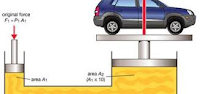
Pascal's Law and Mechanical Advantage ----Pascal's law allows forces to be multiplied.

Generally, the mechanical advantage is calculated as:

MA = (the distance over which force is applied) ÷ (the distance over which the load is moved)

Applied to the system shown below, such as a hydraulic car lift, Pascal's law allows forces to be multiplied.

The cylinder on the left shows a cross-section area of 1 square inch, while the cylinder on the right shows a cross-section area of 10 square inches.

The cylinder on the left has a weight (force) on 1 pound acting downward on the piston, which lowers the fluid 10 inches.

As a result of this force, the piston on the right lifts a 10 pound weight a distance of 1 inch.

The 100 pound load on the 1 square inch area causes an increase in pressure on the fluid in the system.

This pressure is distributed equally throughout and acts on every square inch of the 10 square inch area of the large piston.

As a result, the larger piston lifts up a 1000 pound weight.

The larger the cross-section area of the second piston, the larger the mechanical advantage, and the more weight it lifts.

The formulas that relate to this are shown below:

Area1/Area2= Distance moved 2/Distance moved 1

This system can be thought of as a simple machine (lever), since force is multiplied. The mechanical advantage can be found by rearranging terms in the above equation to

Mechanical Advantage(MA) = D1/D2 = A2/A1

For the sample problem above, the MA would be 10:1 (10 inches/ 1 inch or 10 square inches / 1 square inch).

Take the Edinformatics Challenge

Edinformatics has designed a two part -end of year- 8th grade science test that accesses both "Knowledge and Concepts" (Part I), and "Reasoning and Analysis Skills" (part II). Most of the science material used for the test is consistent with current intermediate school textbooks. Several questions require more rigorous mathematics that is contained within the newly initiated Common Core Standards and the NGSS (Next Generation Science Standards).

https://www.edinformatics.com/math_science/pascals-principle-and-hydraulics.html


You might also like:

..

Hydraulics

CLICK HERE . . . to view . . . 

https://puricare.blogspot.com/2020/12/hydraulics-challenge-your-friends-to.html

...........................................................................................................................................................................................................................................................................................

What are Fluids? 

CLICK HERE . . . to view . . . 

https://puricare.blogspot.com/2019/05/what-are-fluids-fluids-are-substances.html

...........................................................................................................................................................................................................................................................................................

Fluid Dynamics

CLICK HERE . . . to view . . . 

https://puricare.blogspot.com/2019/09/fluid-dynamics-fluid-dynamics-is-one-of.html

...........................................................................................................................................................................................................................................................................................

Hydrostatic Pressure

CLICK HERE . . . to view . . . 

https://puricare.blogspot.com/2019/04/hydrostatic-pressure-fluid-pressure-and.html

...........................................................................................................................................................................................................................................................................................


Tuesday, August 11, 2020

HYDRAULIC HAMMERS - The Hydraulic hammer is a construction equipment that is used for the demolition of a structure and breaking rocks into smaller sizes. It is an attachment on an excavator and works on the principle of hydraulics. It applies high pressure from its small canister which has pressurized hydraulic oil stored in it. They are much more powerful than other hand-held hammers and its force is varied based on the force of piston strokes and its size. The hydraulic hammer is of two types namely – inner valve type and outer valve type. Both types have mostly same components, such as a cylinder which is the most important part of the hydraulic system. A piston is also present in both types of a hydraulic hammer which converts kinetic energy into hammering energy and a front head is featured to support the machine, and one back head which contains the nitrogen gas. Most applications for hydraulic hammers are for mining, rock breaking, concrete breaking and demolition. Many are designed as attachments to mobile equipment such as backhoes and diggers. The hydraulic hammer starts with its main valve in the cylinder. The hydraulic oil is supplied to hammer through this valve. When upward stroke takes place, the pressure in the upper chamber is released by the main valve and through the outlet. Then the high pressure in the lower chamber pushes the piston upwards.

hydraulic hammer
.................................................................................................................................................................
Hydraulic Hammers
What is Hydraulic Hammer and how does it work?
Ramjatab pandit
engineeringinsider.org


hydraulic hammerThe Hydraulic hammer is a construction equipment that is used for the demolition of a structure and breaking rocks into smaller sizes.
It is an attachment on an excavator and works on the principle of hydraulics.
It applies high pressure from its small canister which has pressurized hydraulic oil stored in it.
They are much more powerful than other hand-held hammers and its force is varied based on the force of piston strokes and its size.
hydraulic hammerThe hydraulic hammer is of two types namely – inner valve type and outer valve type.
Both types have mostly same components, such as a cylinder which is the most important part of the hydraulic system.
A piston is also present in both types of a hydraulic hammer which converts kinetic energy into hammering energy and a front head is featured to support the machine, and one back head which contains the nitrogen gas.
Most applications for hydraulic hammers are for mining, rock breaking, concrete breaking and demolition.
Many are designed as attachments to mobile equipment such as backhoes and diggers.
Working of a Hydraulic Hammer
Hydraulic hammer works on the principle of hydraulics by Blaise Pascal which states that “applying pressure on one part of a fluid transfers that pressure to all areas of the fluid, allowing for a multiplication of force”.
Since the oil used is incompressible, it allows the transfer of power instantly with negligible loss.
The hydraulic hammer starts with its main valve in the cylinder.
The hydraulic oil is supplied to hammer through this valve.
When upward stroke takes place, the pressure in the upper chamber is released by the main valve and through the outlet.
Then the high pressure in the lower chamber pushes the piston upwards.
As the piston reaches the upper end of the stroke, the main valve directs the flow to upper chambers that make it high-pressure chamber.
This causes the piston to move downward because of accumulated energy from the gas chamber, hence creating the impact stroke cycle.
The energy is transferred to the tool that uses it to do various tasks.
At the point of impact, the main valve shifts and the pressure from upper chamber is released, enabling the upper stroke to take place.
Most of the hydraulic hammers come with fully enclosed housing over their parts not only to protect them from other materials but to ensure that they last longer.
To increase the safety of equipment on which the hydraulic hammer is attached, the models comprise of shock absorbers at the top that absorbs all the impact and recoil energies.
Moreover, the shock absorber also helps to protect the parts of the hydraulic hammer.
Some of the hydraulic hammers are equipped with steel bushing in their bottom that isolates them from vibration.
Hydraulic hammers are environment-friendly because they produce less noise and pollutants. They are preferred in the places that are sensitive to vibration and noise, as a vibratory hammer may damage the existing structures. 


hydraulic hammer

Sunday, February 2, 2020

DROWNING MACHINE - THE DANGERS OF LOW HEAD DAMS - A low head dam, sometimes simply called a weir, is a small structure that impounds a small amount of water and spans the width of river or stream. Usually made from concrete, the purpose of a low head dams is to raise the water level upstream on a river. This can assist with navigation of the channel by boats, create a drop for generating hydropower, and for water supply and irrigation. Low head dams almost always have subcritical flow upstream. The flow is deep, slow, and tranquil as it makes its way to the dam. But as the flow passes over the weir, it picks up speed and becomes supercritical. When this supercritical flow transitions back to subcritical flow in the slower moving water downstream, it creates a hydraulic jump. These could pose a threat to those using the waterway for recreation. Any location with fast moving water and high turbulence can be dangerous to swimmers or kayakers, but the location of this hydraulic jump can turn a manageable risk into an almost surefire way to drown.

Image result for images weir hydraulic jump
..............................................................................................................................................................
Image result for images weir hydraulic jump Drowning Machine : 
The Dangers of Low Head Dams
Grady Hillhouse
Practical Engineering


Image result for images weir hydraulic jumpDams serve a wide variety of purposes from hydropower to flood control to storage of water for municipal and industrials uses.
But when a dam’s useful purpose fades away, the structure itself still remains.
Dams come in all shapes and sizes, but contrary to what you might think, the most dangerous dams are often the smallest.
A low head dam, sometimes simply called a weir, is a small structure that impounds a small amount of water and spans the width of river or stream.
Usually made from concrete, the purpose of a low head dams is to raise the water level upstream on a river.
This can assist with navigation of the channel by boats, create a drop for generating hydropower, and make water available at intakes for water supply and irrigation.
Thousands of these structures have been constructed over the years to take advantage of natural watercourses and rivers.
The heyday of low head dam construction was actually in the 1800s when mills and factories often relied on waterpower to drive grinding wheels and other equipment.
This was at a time when moving water was the most consistent source of power available in large quantities before widespread adoption of electricity.
Most of these old mills and factories are long gone, and the ones that still survive certainly don’t depend on water for power anymore.
That means many property owners are forced to maintain these old structures that no longer have any practical use.
Or more commonly and much worse, these dams are abandoned by their owner and gradually fall into disrepair.
In the U.S., dam safety regulations focus primarily on the possibility of a dam breaching and causing a flood wave downstream.
But, because low head dams are relatively short, a breach poses minimal danger, so most states don’t keep track of these small structures.
And, especially if they’ve been abandoned, it can be difficult to enforce maintenance requirements on the owners.
Image result for images weir hydraulic jumpBut, even though they pose little danger in the event of a breach, low head dams create a public safety issue that has caused more fatalities in the U.S. than all dam failures in the past 20 years.
To understand why, we first need to know a little bit about open channel hydraulics.
If you haven’t seen my video about hydraulic jumps, I’ll summarize it here. Go back and check out that video if you want to learn more.
Open channel flow - that’s flow not confined within a pipe - has a very important property related to its velocity that governs its behavior.
Slow, tranquil flowing water is called subcritical because waves propagate faster than the flow velocity.
Fast moving water is supercritical because waves move slower than the flow velocity.
Any time a supercritical flow encounters subcritical flow, an interesting phenomenon called a hydraulic jump is formed.
Low head dams almost always have subcritical flow upstream. The flow is deep, slow, and tranquil as it makes its way to the dam.
But as the flow passes over the weir, it picks up speed and becomes supercritical. When this supercritical flow transitions back to subcritical flow in the slower moving water downstream, it creates a hydraulic jump as you can see here in my model flume.
It’s easy to see why these types of structures could pose a threat to those using the waterway for recreation.
Any location with fast moving water and high turbulence can be dangerous to swimmers or kayakers, but the location of this hydraulic jump can turn a manageable risk into an almost surefire way to drown.
The depth of the flow downstream of a dam is called the tailwater, and it controls the location of the hydraulic jump.
In my model, I can adjust the elevation of the tailwater by adding or removing these stoplogs.
When tailwater is low, the hydraulic jump forms away from the dam. This is a fully developed jump that follows the traditional shape and flow patterns.
If I send down this piece of wood as a kayaker surrogate, it experiences some turbulence as it passes over the weir and through the jump but, it doesn’t have much trouble escaping downstream.
But, as the tailwater rises the jump moves closer and closer to the dam. Eventually if the tailwater is high enough, the hydraulic jump will reach the dam.
This condition is called a submerged or drowned jump. It may look fairly innocuous, but this is when things get dangerous.
Let’s send down our kayaker surrogate to see why. A submerged hydraulic jump creates an area of recirculation immediately downstream of the dam sometimes called a “keeper” for obvious reasons.
Image result for images weir hydraulic jumpThe jet of the hydraulic jump surfaces downstream causing a boil point. Sometimes this is easy to see and sometimes it’s not.
Either way, objects or people can will only be able to escape a submerged hydraulic jump if they are able to get beyond this boil point.
And, any rescuers who approach a submerged jump from downstream run the risk of being drawing into the hydraulic themselves.
The recirculating currents that trap recreators is dangerous enough on its own but there are other factors contributing to the danger at low head dams.
These currents also trap large debris between the strong hydraulic forces and the hard concrete surface of the dam which can batter someone trapped in the keeper.
The water is often cold, increasing the potential for hypothermia and further disorientation.
The turbulence of the hydraulic jump entrains a lot of air, reducing the buoyancy of a swimmer. And, low head dams often span the entire width of the river, meaning there is no still water nearby that can be used as a safe haven.
This is exactly why the low head dam is called the perfect drowning machine. All these factors added together create a situation that’s almost impossible to survive.
There are a lot of ways to mitigate this issue. The simplest option is just to keep people away from these structures.
Some states require that exclusion zones be established to make sure that kayakers safely portage dams instead of trying to run them.
Good signage and buoys as warnings can sometimes be enough to keep people safe. Another option is to modify the structure to reduce the potential for recirculating currents.
Researchers have proposed various retrofits to existing dams to improve flow conditions when tailwater is high. Of course, the most obvious (but also most expensive) way to address the issue is to remove these dams altogether.
In many cases they are no longer serving an important role, and removing dams can help restore ecosystems and improve connectivity for aquatic species in addition to removing a hazard.
If you’re swimming or paddling on a river with a low head dam, don’t underestimate the danger of these powerful hydraulic forces.
Different flow conditions on the river can dramatically change the behaviour of the hydraulic jump, as we saw, so be careful. Thank you for watching and let me know what you think!

Hey, I’m Grady Hillhouse and this is Practical Engineering! I am a husband, a professional civil engineer, and educational video producer in San Antonio, Texas.
Randall Munroe said, "You can look at practically any part of anything manmade around you and think, 'Some engineer was frustrated while designing this.' It's a little human connection." My goal for Practical Engineering is simple: to increase exposure and interest in the field of engineering.
Of course, as a civil engineer, much of my content is geared towards infrastructure and the stories behind the humanmade world we live in. I like to help people make a connection between themselves and their constructed environment. In order for people to care about infrastructure, they need to be interested in the engineering behind it and see people who are passionate about finding innovative ways to meet humanity’s basic needs. I really believe this and it’s important to me. I hope that my videos are helpful to you and encourage you to take opportunities to be an advocate for civil engineering.
Image result for images weir hydraulic jump