Showing posts with label Foundations. Show all posts

Thursday, August 27, 2020

PRE-ENGINEERED BUILDINGS - Pre-engineered buildings are factory-built buildings of steel that are shipped to site and bolted together. What distinguishes them from other buildings is that the contractor also designs the building - a practice called design & build. This style of construction is ideally suited to industrial buildings and warehouses; it is cheap, very fast to erect, and can also be dismantled and moved to another site - more on that later. These structures are sometimes called 'metal boxes' or 'tin sheds' by laymen - they are essentially rectangular boxes enclosed in a skin of corrugated metal sheeting. Great speed is achieved because while the foundations and floor slab are being constructed, the beams and columns - the structural system - are being fabricated in the factory. Once the foundations and floor are done, the columns are shipped to the site, lifted into place by cranes, and bolted together. The structural system of pre-engineered steel buildings give it its speed and flexibility. This system consists of factory-fabricated and factory-painted steel column and beam segments that are simply bolted together at site. The columns and beams are custom-fabricated I-section members that have an end plate with holes for bolting at both ends. These are made by cutting steel plates of the desired thickness, and welding them together to make I sections.


...............................................................................................................................................................
Pre-Engineered Buildings
understandconstruction.com


Pre-engineered buildings are factory-built buildings of steel that are shipped to site and bolted together.
What distinguishes them from other buildings is that the contractor also designs the building - a practice called design & build.
This style of construction is ideally suited to industrial buildings and warehouses; it is cheap, very fast to erect, and can also be dismantled and moved to another site - more on that later.
These structures are sometimes called 'metal boxes' or 'tin sheds' by laymen - they are essentially rectangular boxes enclosed in a skin of corrugated metal sheeting. 
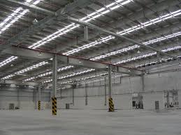
This pre-engineered industrial building, designed by one of the authors of understandconstruction.com,
 has polycabonate strips in the roof to allow for uniform natural lighting. Ten foot (3m) high concrete
block walls on the periphery contain windows and provide security; above that,  the only walling
material is a thin corrugated metal sheet.
Great speed is achieved because while the foundations and floor slab are being constructed, the beams and columns - the structural system - are being fabricated in the factory.
Once the foundations and floor are done, the columns are shipped to the site, lifted into place by cranes, and bolted together.
STRUCTURAL SYSTEMS
The structural system of pre-engineered steel buildings give it its speed and flexibility.
This system consists of factory-fabricated and factory-painted steel column and beam segments that are simply bolted together at site.
The columns and beams are custom-fabricated I-section members that have an end plate with holes for bolting at both ends.
These are made by cutting steel plates of the desired thickness, and welding them together to make I sections.
The cutting and welding is done by industrial robots for speed and accuracy; operators will simply feed a CAD drawing of the beams into the machines, and they do the rest.
This production line style of work makes for great speed and consistency in fabrication.
Pre-engineered building before the roof skin has been installed. Note that the shape  of the
beams follows the forces in them; the beams are deeper where the forces are greater.
The shape of the beams can be tailored to optimum structural efficiency: they are deeper where the forces are greater, and shallow where they are not.
This is one form of construction in which the structures are designed to carry exactly the loads envisioned, and no more.
ERECTION
Each piece of the system is very much alike - an I section with end plates for bolting.
The painted steel sections are lifted into place by crane, and then bolted together by construction workers who have climbed to the appropriate position.
In large buildings, construction can start with two cranes working inwards from both ends; as they come together, one crane is removed and the other finishes the job.
Usually, each connection calls for six to twenty bolts to be installed. Bolts are to be tightened to exactly the right amount of torque using a torque wrench.
FOUNDATIONS AND FLOOR SLAB
The foundations for pre-engineered metal buildings are made with conventional concrete systems, usually open foundations.
Since these structures are usually quite large, they attract a fair amount of wind forces.
Wind can cause a net upwards force on a building, called uplift.
Since these structures are very light (they can weigh as little as 50 kg per square meter, excluding the foundations and floor slab), the foundations are designed to firmly anchor the structures to the ground, preventing them from being blown away by the wind.
The floor system for industrial and storage buildings is usually a thick (about 8" to 12" / 200 to 300mm) concrete grade slab that rests directly on the prepared earth beneath it.
The concrete can be topped with a thin, abrasion resistant smooth coating called an epoxy floor or polyurethane floor if desired.
CLADDING AND ROOFING - THE BUILDING ENVELOPE
The most economical cladding for these structures is light corrugated metal sheeting, on both the roof and the external walls.
These steel sheets, barely 0.5mm thick, are coated with an aluminum-zinc alloy for corrosion protection on both sides, and come with an attractive, durable paint finish on the outside.
These sheets are installed over a grid of purlins, a steel member that rests on the main structural frame and supports the roofing material.
In pre-engineered buildings, cold formed Z sections are the member of choice for purlins.
Before installing the sheets, contractors will install layers of insulation and vapor barriers.
Rolls of glass wool or mineral wool are the most common type of insulation for such buildings.
Since there is no inner wall over which to fix these layers, a layer of galvanized chicken wire mesh is first laid over the purlins.
Over this, the insulation and vapor barriers are laid, and then the corrugated sheets are laid.
The sheets are fixed with self tapping screws that run through the sheets and layers of insulation directly into the purlins.
The purlins, chicken mesh and insulation are thus visible from below, and can be left as such or covered with a false ceiling.
Polycarbonate skylights can be installed in the roof sheeting to create natural lighting.
It is common for industrial buildings to have a masonry wall upto a height of 10 or 15 feet (3 to 5m).
This allows doors and windows to be easily fitted, and provides security.
This wall can be built behind the metal sheeting, making it invisible from the outside.

 This is a site that explains the art and science of building construction in great clarity and detail.  Our goal is to make you understand concepts in building construction.
Written by architects and engineers, the content on the site is actually a result of accumulated years of work experience at building construction sites and design offices.  This expert knowledge of building construction is not available in textbooks!
We also take great pains to ensure that our quality of writing is of a high standard.  We aim to take complicated situations and make them simple and clear, as well as to provide content that is interesting to industry experts and newcomers alike.  Do let us know where we succeed - and where we fail - in this task.

Friday, January 3, 2020

PILE FOUNDATIONS - Pile foundations are capable of taking higher loads than spread footings. A pile is basically a long cylinder of a strong material such as concrete that is pushed into the ground to act as a steady support for structures built on top of it. As pile foundations carry a lot of load, they must be designed very carefully. A good engineer will study the soil the piles are placed in to ensure that the soil is not overloaded beyond its bearing capacity. Every pile has a zone of influence on the soil around it. Care must be taken to space the piles far enough apart so that loads are distributed evenly over the entire bulb of soil that carries them, and not concentrated into a few areas. Engineers will usually group a few piles together, and top them with a pile cap. A pile cap is a very thick cap of concrete that extends over a small group of piles, and serves as a base on which a column can be constructed. The load of this column is then distributed to all the piles in the group.


..............................................................................................................................................................
Pile Foundations
understandconstruction.com


A pile is basically a long cylinder of a strong material such as concrete that is pushed into the ground to act as a steady support for structures built on top of it.
Pile foundations are used in the following situations:
When there is a layer of weak soil at the surface. This layer cannot support the weight of the building, so the loads of the building have to bypass this layer and be transferred to the layer of stronger soil or rock that is below the weak layer.
When a building has very heavy, concentrated loads, such as in a high-rise structure, bridge, or water tank.
Pile foundations are capable of taking higher loads than spread footings.
There are two fundamental types of pile foundations (based on structural behaviour), each of which works in its own way.
End Bearing Piles
In end bearing piles, the bottom end of the pile rests on a layer of especially strong soil or rock.
The load of the building is transferred through the pile onto the strong layer. In a sense, this pile acts like a column.
The key principle is that the bottom end rests on the surface which is the intersection of a weak and strong layer.
The load therefore bypasses the weak layer and is safely transferred to the strong layer.
Friction Piles
Friction piles work on a different principle. The pile transfers the load of the building to the soil across the full height of the pile, by friction.
In other words, the entire surface of the pile, which is cylindrical in shape, works to transfer the forces to the soil.
To visualise how this works, imagine you are pushing a solid metal rod of say 4mm diameter into a tub of frozen ice cream.
Once you have pushed it in, it is strong enough to support some load. The greater the embedment depth in the ice cream, the more load it can support.
This is very similar to how a friction pile works. In a friction pile, the amount of load a pile can support is directly proportionate to its length.
WHAT ARE PILES MADE OF?
Piles can be made of wood, concrete, or steel.
In traditional construction, wooden piles were used to support buildings in areas with weak soil.
Wood piles are still used to make jetties. For this one needs trees with exceptionally straight trunks.
The pile length is limited to the length of a single tree, about 20m, since one cannot join together two tree trunks.
The entire city of Venice in Italy is famous for being built on wooden piles over the sea water.
Pile Foundations
Concrete piles are precast, that is, made at ground level, and then driven into the ground by hammering - more on that later.
Steel H-piles can also be driven into the ground. These can take very heavy loads, and save time during construction, as the pile casting process is eliminated.
No protective coating is given to the steel, as during driving, this would be scraped away by the soil. In areas with corrosive soil, concrete piles should be used.
HOW PILES ARE USED
As pile foundations carry a lot of load, they must be designed very carefully.
A good engineer will study the soil the piles are placed in to ensure that the soil is not overloaded beyond its bearing capacity.
Every pile has a zone of influence on the soil around it.
Care must be taken to space the piles far enough apart so that loads are distributed evenly over the entire bulb of soil that carries them, and not concentrated into a few areas.
Engineers will usually group a few piles together, and top them with a pile cap.
A pile cap is a very thick cap of concrete that extends over a small group of piles, and serves as a base on which a column can be constructed. The load of this column is then distributed to all the piles in the group.
HOW PILES ARE CONSTRUCTED
Cast-in-place piles are made in the following steps:
hammer a thin-walled steel tube into the ground
remove all earth left inside the tube
lower a steel reinforcement cage into the tube
cast the pile by pouring wet concrete into the tube
The thin walled steel tube is called the casing, and only serves to form a secure mould for casting concrete that is free from earth and debris. It has no structural role to play after the casting is complete.
Some soils are highly cohesive, meaning that if one drills a hole into the soil that is say 1 foot wide by 50 feet deep, then the soil holds the shape of the hole and does not collapse into the hole and block it.
If such soil is present at the site, then one does not need to leave a casing in place: one can use the casing to drill the hole for the pile, and then remove it, and then cast the pile in place.
This saves costs as the same casing tube can be used to drill holes for all the piles.
Precast Driven Piles are first cast at ground level and then hammered or driven into the ground using a pile driver.
This is a machine that holds the pile perfectly vertical, and then hammers it into the ground blow by blow.
Each blow is struck by lifting a heavy weight and dropping it on the top of the pile - the pile is temporarily covered with a steel cap to prevent it from disintegrating.
The pile driver thus performs two functions - first, it acts as a crane, and lifts the pile from a horizontal position on the ground and rotates it into the correct vertical position, and second, it hammers the pile down into the ground.
Piles should be hammered into the ground till refusal, at which point they cannot be driven any further into the soil.
SPECIAL PILES
Pile driving is very noisy and causes massive vibrations through the soil. For this reason, it is sometimes difficult to use them in sensitive locations.
For example, if an operational hospital or science lab is to be extended, driving piles would cause unwanted disturbance.
Their use is also restricted in residential areas in many countries. The vibrations could also cause structural damage to older buildings that are close by.
In such situations it is possible to use micropiling or helical piling, neither of which rely on hammering.
Micropiles or minipiles are small piles that are constructed in the following way:
Step 1: a hole a little larger than the pile diameter and the full length of the pile is dug into the ground using an apparatus like a soil boring machine.
Step 2: a precast concrete pile is lowered or pushed into the hole.
Step 3: a concrete grout is poured into the gap between the pile and the earth.
Helical piles are steel tubes that have helical (spiral) blades attached to them.
These can be drilled into the ground, meaning that the pile acts as a giant drill bit, and is rotated and pushed into the ground from above, much like a screw drills into wood.
Once the steel pile is driven into the ground, a pile cap is poured on top of the pile to prepare it for the construction above.

This is a site that explains the art and science of building construction in great clarity and detail.  Our goal is to make you understand concepts in building construction.
Written by architects and engineers, the content on the site is actually a result of accumulated years of work experience at building construction sites and design offices.  This expert knowledge of building construction is not available in textbooks!
We also take great pains to ensure that our quality of writing is of a high standard.  We aim to take complicated situations and make them simple and clear, as well as to provide content that is interesting to industry experts and newcomers alike.  Do let us know where we succeed - and where we fail - in this task.
We are a free site - we cover our costs by advertising, so do feel free to click on ads that interest you!

Friday, November 22, 2019

EXPANSIVE SOIL AND EXPANSIVE CLAY - The hidden force behind basement and foundation problems – When expansive soils absorb water, they increase in volume. The more water they absorb, the more their volume increases. This change in volume can exert enough force on a building or other structure to cause damage. Cracked foundations, floors, and basement walls are typical types of damage done by swelling soils. Damage to the upper floors of the building can occur when motion in the structure is significant. Expansive soils will also shrink when they dry out. This shrinkage can remove support from buildings or other structures and result in damaging subsidence. Fissures in the soil can also develop. These fissures can facilitate the deep penetration of water when moist conditions or runoff occurs.

foundation cracks caused by expansive soils
Building damage: Note displaced bricks and inward deflection of foundation.
...................................................................................................................................................................
Expansive Soil and Expansive Clay
cracks in expansive soil
Cracks in expansive soil: Desiccation cracks in soil caused by drying. 
The hidden force behind basement and foundation problems
Article by: Hobart M. King, Ph.D., RPG


What is an "Expansive Soil"?
Expansive soils contain minerals such as smectite clays that are capable of absorbing water. When they absorb water, they increase in volume.
The more water they absorb, the more their volume increases. Expansions of ten percent or more are not uncommon. This change in volume can exert enough force on a building or other structure to cause damage.
Cracked foundations, floors, and basement walls are typical types of damage done by swelling soils. Damage to the upper floors of the building can occur when motion in the structure is significant.
In a typical year in the United States, expansive soils cause a greater financial loss to property owners than earthquakes, floods, hurricanes, and tornadoes combined.
Expansive soils will also shrink when they dry out. This shrinkage can remove support from buildings or other structures and result in damaging subsidence.
Fissures in the soil can also develop. These fissures can facilitate the deep penetration of water when moist conditions or runoff occurs.
This cycle of shrinkage and swelling places repetitive stress on structures, and damage worsens over time.
How Many Buildings are at Risk?
Expansive soils are present throughout the world and are known in every US state. Every year they cause billions of dollars in damage.
The American Society of Civil Engineers estimates that 1/4 of all homes in the United States have some damage caused by expansive soils.
In a typical year in the United States, they cause a greater financial loss to property owners than earthquakes, floods, hurricanes, and tornadoes combined.
Even though expansive soils cause enormous amounts of damage, most people have never heard of them.
This is because their damage is done slowly and cannot be attributed to a specific event.
The damage done by expansive soils is then attributed to poor construction practices or a misconception that all buildings experience this type of damage as they age.
Homeowners Insurance and Expansive Soils
Damage to a home caused by expansive soils can be catastrophic for a homeowner. Why?
Most homeowners insurance policies do not cover damage caused by expansive soils. The cost of repairs and mitigation can be extremely high - it sometimes exceeds the value of the home.
In many cases the homeowner noticed the problem, didn’t realize its severity, didn’t realize that it was progressing, and the problem progressed to a point where repair didn’t make economic sense.
Expandable, Shrink-Swell, Heavable Soils?
Expandable soils are referred to by many names. "Expandable soils," "expansive clays," "shrink-swell soils," and "heavable soils" are some of the many names used for these materials.
The problem is so unfamiliar to the average homeowner that they don't know what to call it.
Expansive Soils Map
The map on this page shows the generalized geographic distribution of soils that are known to have expandable clay minerals which can cause damage to foundations and structures. It also includes soils that have a clay mineral composition which can potentially cause damage.
How to Interpret the Map
The map is meant to show general trends in the geographic distribution of expansive soils. It is not meant to be used as a property evaluation tool. It is useful for learning areas where expansive soils underlie a significant portion of the land and where expansive soils might be a localized problem.
All construction projects should include a soil analysis to identify the types of soil present and determine their expansive properties. Local occurrences of expansive soils can be found in all of the soil categories shown on this map.
Why Do These Soils Expand?
Soils are composed of a variety of materials, most of which do not expand in the presence of moisture.
However, a number of clay minerals are expansive. These include: smectite, bentonite, montmorillonite, beidellite, vermiculite, attapulgite, nontronite, and chlorite. There are also some sulfate salts that will expand with changes in temperature.
When a soil contains a large amount of expansive minerals, it has the potential of significant expansion. When the soil contains very little expansive minerals, it has little expansive potential.
Changes in Moisture Content Trigger Damage
When expansive soils are present, they will generally not cause a problem if their water content remains constant. The situation where greatest damage occurs is when there are significant and repeated moisture content changes.
The Bottom Line
It is possible to build successfully and safely on expansive soils if stable moisture content can be maintained or if the building can be insulated from any soil volume change that might occur.
The procedure for success is as follows:
·         Testing to identify any problems
·         Design to minimize moisture content changes and insulate from soil volume changes
·         Build in a way that will not change the moisture conditions of the soil
·         Maintain a constant moisture environment after construction
Expert assistance is usually needed to do these things successfully.

Hobart M. King, Ph.D., GIA GG
Hobart M. King is the owner and publisher of Geology.com. He is a geologist with over 40 years of experience, has a Ph.D. in geology, and is a GIA graduate gemologist. Much of his work has focused on coal geology, industrial minerals, gemology, geologic hazards, and geoscience education.
He has authored many of the internet’s most popular articles about rocksminerals and gems. He writes most of the content published on Geology.com and compiles its daily news. His writing is read by over a million people each month, making him one of the world’s most widely read geologists.
Dr. King earned a Ph.D. and an M.S. in geology from West Virginia University; a B.S. in geology from California University of Pennsylvania; and, a Graduate Gemologist Diploma from the Gemological Institute of America. He is a registered professional geologist in the Commonwealth of Pennsylvania.
He has worked as a geologist in a variety of settings since 1975.
https://geology.com/articles/expansive-soil.shtml
deflected basement wall
Deflected basement wall: Inward deflection of a basement wall and pilasters. The plumb-bob reveals 9 inches of inward displacement.
expansive soils map
Expansive soils map: The map above is based upon "Swelling Clays Map of the Conterminous United States"

Sunday, November 10, 2019

BUILDING FOUNDATION - In order to be able to start the foundation, the building pad needs to be complete. Dirt needs to be compacted and rough graded to the correct elevation. The batter boards and string lines will allow you to get a true picture of the footprint. The batter boards and string lines will allow you to get a true picture of the footprint of the house and finish floor elevation. The foundation forms can be wood as in most residential construction or metal as in commercial construction. Once the forms are set, they need to be braced off in order to prevent the concrete from pushing the forms out. Concrete is one of the main building products used in the construction of a house. Depending on where the concrete is used in the construction process, it can become a very critical factor in the overall structural strength of the house.

Image result for images Building Foundation
....................................................................................................................................
Image result for images Building Foundation
Building Foundation
constructionjargon.com


Foundation - First Task
The location of the foundation is determined by the site survey or plot plan.
The plot plan will show all property line setbacks, dimensions, easements, and any other normally determined by flood plane restrictions or city and county codes.
The surveyor can provide a marker or benchmark that serves restrictions that might be required.
Another important item required for the foundation is the elevation of the foundation.
The elevation is normally determined by flood plane restrictions or city and county codes.
The surveyor can provide a marker or benchmark that serves as a reference to establish the finish floor elevation (FFE).
In order to be able to start the foundation, the building pad needs to be complete.
If fill dirt is required, it needs to be compacted and rough graded to the correct elevation Once the pad is complete and the corners established, batter boards can be put up.
The batter boards and string lines will allow you to get a true picture of the footprint.  
Once the pad is complete and the of the house and finish floor elevation. After the string lines are checked for correct dimensions and corners established, batter boards can be put up.
The batter boards and string lines will allow you to get a true picture of the footprint of the house and finish floor elevation.
After the string lines are checked for correct dimensions and being square, you will be ready to start putting up forms and digging footings.
The foundation forms can be wood as in most residential construction or metal as in commercial construction.
Once the forms are set, they need to be braced off in order to prevent the concrete from pushing the forms out.
After the foundation forms are set and braced, the underground plumbing can be installed. The plumber can use the form boards to lay out the position of the plumbing walls and pull string lines.
With the plumbing wall lines in place, the plumber can dig the plumbing ditches and be sure that the plumbing is installed correctly.
After the plumbing is installed, the ditches should be left uncovered until inspected by county or city
inspectors.
Sanitary lines are checked for slope and for leaks. Sanitary lines should have at least a 1/4 inch slope per foot.
The sewer lines are checked for leaks by using a ten foot stack test.
The stack test is accomplished by extending the main vent stack, usually a 3 inch PVC vent up ten feet.
The whole house sewer system is then filled with water up to the top of the ten foot vent stack. All the underground plumbing connections are then checked for leaks.
Concrete is one of the main building products used in the construction of a house. Depending on where the concrete is used in the construction process, it can become a very critical factor in the overall structural strength of the house.
Just because the concrete comes premixed in the concrete truck does not mean that the concrete is always good.
In normal residential concrete, the first conversations might be with the concrete company's outside sales person.
The size of the foundation and how much concrete will be required are usually the first questions to be answered.
The quantity of concrete is expressed in "yards". One cubic yard of concrete is equal to
twenty-seven cubic feet of concrete.
An example would be if there was a hole three feet wide, three feet long, and three feet deep it would require one yard of concrete to fill the hole.
Another value that is used when pouring sidewalks and driveways is that a yard of concrete will cover eighty one square feet of area (driveway or sidewalk) when the concrete is four inches thick.
The next issue discussed might be the strength of the concrete.
Years ago, the only strength concrete used in house foundations was 2000 psi (pounds per square inch) concrete. It's not unusual today to see builders pouring 3000 psi and 4000 psi concrete, depending on the size and complexity of the project.
Some of the larger homes are designed by an architect and might require a structural engineer. The structural engineer might require mix designs from the concrete company for his approval.
The sales person might ask next what kind of "slump" is required. This is sometimes where the concrete subcontractor and the builder might try to reach a compromise.
The lower the slump the greater the strength but the harder the concrete is to work. The higher the slump the lesser strength but the easier
the concrete is to work.
When a structural engineer is involved, he might specify that the concrete is to be 3000 psi with a three to five-inch slump.
If this is specified, it is very important to stay within these limits do not allow anyone to add water to the mix on site without permission from the individual doing the testing.
If the concrete is being pumped, there are additives that can be added to the mix in order to
allow a higher slump but not jeopardize the strength of the concrete.
These additives can also be used in dry and windy climates to allow a wetter mix and hopefully prevent surface cracking due to the fast dehydration of the concrete.
If the concrete is tested, the slump might be checked every fifty yards and the cylinders might be taken at the same interval.
Concrete cylinders are taken and tested to verify the compressive strength of the cured concrete.
The cylinders are compressed and broke at specified intervals. A cylinder broke after 28 days should break at the designed strength or greater.
Also, usually the temperature of the concrete will be checked at this time. The temperature of the concrete might become more of a factor in the summer rather than the winter.
A rule of thumb might be that if the concrete temperature is above 95 degrees it is not acceptable to pour in the foundation or footings.
Sometimes a good starting point to monitor the temperature of the concrete in a truck is to check the ticket and see when the truck was loaded at the plant.
In warmer climates, the longer the concrete is in the truck the hotter the mix. In cooler climates the temperature might not be out of range but the time in the truck might become a factor.
Usually a rule of thumb might be that, if it has been forty five minutes to an hour since the truck was loaded, the load may have started setting up and might not be acceptable to use.
As you can see there are a few more things to consider in foundation concrete other than just pouring the concrete out of the truck.
As in most any other construction process, a little pre-planning and basic knowledge might prevent a major mistake that could cost a lost of time and money.
As stated previously, the foundation is one of the most important phases in the construction of a house. This phase will require you to be familiar with reading plans, dimensions, and formulas to determine quantities of required materials.
Some of the more common quantities will be expressed as length, width, depth, linear feet, board feet, square feet, cubic feet and cubic yards. All the materials in the foundation will be ordered and bought with one of these descriptions.
In order for you to be able to estimate and order materials correctly, there are certain formulas that can help you calculate the correct quantities of concrete.
The following formulas are ones that will be necessary in order to calculate and order the required material for your foundation.
Linear Feet is probably the simplest quantity to calculate. Lumber yards sometimes sell lumber by the linear foot which makes it easy to calculate the
cost per piece.
Linear feet = number of items X the item length
220- 2 x 4's lumber X 16 feet in length = 3520 linear feet
Lumber is one of the main items that might be bought by the linear foot for a foundation. If you dig footings, labor might be charged by the linear foot.
Board Feet will add two other dimensions to calculating the cost of materials. Lumber suppliers sometimes sell their lumber per thousand board feet.
A board foot is one linear foot of lumber - one foot wide - one inch thick. A 1x12 piece of pine which is 12 feet long will equal 12 board/feet.
In the same way a 2x6 piece of pine 12 feet long will equal 12 board/feet.
Board feet = Linear feet X ((thickness inches X width inches) / 12 inches)
(3520 linear feet of 2x4) X ((2-inches X 4 inches) / 12 inches) = 2347 Board Feet
Lumber may be sold by the board foot form the building supply. The board foot price will be expressed so much per thousand board feet.
Example: 2 x 6’s might be sold as 565.00 per M (Thousand board feet). This will equal .565 cents per board foot.
Square Feet is a simple process of multiplying the length X the width. You will need to know how many square feet there is in the foundation in order to estimate how much vapor barrier to buy and to determine how much the termite pre-treat will cost.
Square Feet = Length X Width
Cubic Feet adds one other dimension to square feet. This dimension is depth. Items that require you to know the amounts of cubic feet are fill dirt and concrete.
Concrete and fill dirt are both sold by the cubic yard. There is 27 cubic feet in a cubic yard of fill dirt and concrete.
Cubic Feet = Length X Width X depth
Cubic Yard is used to determine how yards of concrete or fill dirt might be needed for the job. There is 27 cubic feet in a cubic yard of fill dirt and
concrete.
Cubic Yard = Total Cubic Feet / 27 cubic feet

I have over thirty years experience in residential construction. I have managed projects from
one single family home to projects consisting of over four hundred homes. During the past
thirty years, my projects have demanded a knowledge of every aspect of construction including
site work, utilities, streets, playgrounds, club houses, swimming pools, and landscaping. I have
experienced the ups and downs of the industry and have probably heard every excuse there is
for not wanting to do a job a particular way. I always have had the philosophy that if I did not
know as much or more about the task being done than the sub doing the work, I would be at a
disadvantage. I have tried to put together some topics and articles that should help someone
not familiar with construction to get a better knowledge of particular tasks in the construction of
a home and be able to talk the talk during the process. The topics in this website are not
necessarily true for all parts of the country. The construction process will change depending on
soil conditions and climate. I appreciate your visit to my site and hope that your construction
experience is good.  
Image result for images Building Foundation