Showing posts with label Mechanical advantage. Show all posts

Friday, October 23, 2020

LEVERS - Mechanical advantage - Bolt cutters can deliver a staggering force of 20 kilonewtons, that is the equivalent of around 2,040 kilograms. It is even more impressive when you think that this is done by the person only applying a force on the handles equivalent to 25 kilograms or 250 kilonewtons - By using a lever Jonathon can lift a load of 3000N using an effort of just 300N. We say that the lever has a mechanical advantage. Bolt cutters can deliver a staggering force of 20 kilonewtons, that is the equivalent of around 2,040 kilograms. It is even more impressive when you think that this is done by the person only applying a force on the handles equivalent to 25 kilograms or 250 kilonewtons. Second order levers - A lever that has the load between the fulcrum and the effort is known as a second order lever. Once again, the further away the effort is from the fulcrum and the load the greater the mechanical advantage of the lever. Third order levers - A third order lever is one which has the effort between the fulcrum and the load. Such levers do not have good mechanical advantage. In fact they have mechanical disadvantage. The effort is closer to the fulcrum than the load. The effort is always greater than the load. However, one advantage of such levers is that the distance moved by the load is greater than the distance moved by the effort. Cranes such as the one on the left are examples of third order levers. As you can see the effort is between the load, at the top, and the fulcrum. The advantage of this lever system is that the load moves through a greater distance than the effort. This is desirable when the crane needs to lift loads high above the ground. Tweezers are another example of a third order lever.

..........................................................................................................................................................................................................................................................................................................

Levers

Mechanical advantage.


Bolt cutters can deliver a staggering force of 20 kilonewtons, that is the equivalent of around 2,040 kilograms. It is even more impressive when you think that this is done by the person only applying a force on the handles equivalent to 25 kilograms or 250 kilonewtons.    

dynamicscience.com.au


By using a lever Jonathon can lift a load of 3000N using an effort of just 300N. We say that the lever has a mechanical advantage.

To calculate just how much mechanical advantage, we use the expression below.

Mechanical advantage = 3000/300

=> 10

Look at the lever system on the right. A load of 30N is supported by a 10N effort. What is its mechanical advantage?

Scan the image for the answer

Mechanical advantage is 3.

Stephen pushes down with a force of 60N to just lift the load off the ground. What is the mechanical advantage of the lever?

Scan the image for the answer

Mechanical advantage is 5.

Stephen pushes down with a force of 300N to just lift the load off the ground. What is the mechanical advantage of the lever?

Scan the image for the answer

Mechanical advantage is 10

Bolt cutters can deliver a staggering force of 20 kilonewtons, that is the equivalent of around 2,040 kilograms. 

It is even more impressive when you think that this is done by the person only applying a force on the handles equivalent to 25 kilograms or 250 kilonewtons.    

Look at the animation on the right. Suggest how this magnification of force is achieved.


Second order levers


A lever that has the load between the fulcrum and the effort is known as a second order lever.


Once again, the further away the effort is from the fulcrum and the load the greater the mechanical advantage of the lever.


Explain why a wheel barrow and a nutcracker are examples of second order levers.


Identify the fulcrum, load and effort.    


Identify the fulcrum, load and effort.


Third order levers

A third order lever is one which has the effort between the fulcrum and the load.


Such levers do not have good mechanical advantage. 


In fact they have mechanical disadvantage. The effort is closer to the fulcrum than the load. 

The effort is always greater than the load. 

However, one advantage of such levers is that the distance moved by the load is greater than the distance moved by the effort. 

Cranes such as the one on the left are examples of third order levers. 

As you can see the effort is between the load, at the top, and the fulcrum. 

The advantage of this lever system is that the load moves through a greater distance than the effort. 

This is desirable when the crane needs to lift loads high above the ground.

Tweezers are another example of a third order lever.

Look at the image on the left. Identify the fulcrum, load and effort.

Is the arm an example of a third order lever? Explain.

http://www.dynamicscience.com.au/tester/solutions1/hydraulicus/simplemachineslevers4.htm

Friday, October 16, 2020

PASCAL'S PRINCIPLE AND HYDRAULICS - Pascal's Principle - Blaise Pascal was a French mathematician, physicist and religious philosopher who lived in the mid-seventeenth century. He made some significant observations about fluid and pressure. He noticed that the shape of a container had no effect on pressure. He also noticed that pressure applied to an enclosed fluid is transmitted undiminished to every part of the fluid, as well as to the walls of the container. When it says "enclosed fluid," that means that in order for Pascal's Law to be true, you have to be looking at a liquid in a closed container. Hydraulic systems use incompressible fluids, such as oil or water, to transmit forces from one location to another within the fluid. Hydraulics are used in most breaking systems. Pascal's law states that when there is an increase in pressure at any point in a confined fluid, there is an equal increase at every other point in the container. Therefore Pascal's law can be interpreted as saying that any change in pressure applied at any given point of the fluid is transmitted undiminished throughout the fluid. Imagine if you have a U-tube filled with water and pistons are placed at each end, pressure exerted against the left piston will be transmitted throughout the liquid and against the bottom of the right piston. The pressure that the left piston exerts against the water will be exactly equal to the pressure the water exerts against the right piston.

.....................................................................................................................................................................................................................................................................................................................................................................................................

Pascal's Principle and Hydraulics

edinformatics.com


Pascal's Principle

Blaise Pascal was a French mathematician, physicist and religious philosopher who lived in the mid-seventeenth century.

He made some significant observations about fluid and pressure.

He noticed that the shape of a container had no effect on pressure.

He also noticed that pressure applied to an enclosed fluid is transmitted undiminished to every part of the fluid, as well as to the walls of the container.

When it says "enclosed fluid," that means that in order for Pascal's Law to be true, you have to be looking at a liquid in a closed container.

Pascal's Principle and Hydraulics

Hydraulic systems use incompressible fluids, such as oil or water, to transmit forces from one location to another within the fluid.

Hydraulics are used in most breaking systems.

Pascal's law states that when there is an increase in pressure at any point in a confined fluid, there is an equal increase at every other point in the container.

Therefore Pascal's law can be interpreted as saying that any change in pressure applied at any given point of the fluid is transmitted undiminished throughout the fluid.

How do Hydraulics Work?

Imagine if you have a U-tube filled with water and pistons are placed at each end, pressure exerted against the left piston will be transmitted throughout the liquid and against the bottom of the right piston.

The pressure that the left piston exerts against the water will be exactly equal to the pressure the water exerts against the right piston.

Now suppose the tube on the right side is made wider and a piston of a larger area is used; for example, the piston on the right has 10 times the area of the piston on the left.

If a 1 N load is placed on the left piston, an additional pressure due to the weight of the load is transmitted throughout the liquid and up against the larger piston.

The additional pressure is exerted against the entire area of the larger piston.

While the pressure exerted is the same, since there is 10 times the area, 10 times as much force is exerted on the larger piston.

Thus, the larger piston will support a 10 N load - ten times the load on the smaller piston.

Pascal's Law and Mechanical Advantage ----Pascal's law allows forces to be multiplied.

Generally, the mechanical advantage is calculated as:

MA = (the distance over which force is applied) ÷ (the distance over which the load is moved)

Applied to the system shown below, such as a hydraulic car lift, Pascal's law allows forces to be multiplied.

The cylinder on the left shows a cross-section area of 1 square inch, while the cylinder on the right shows a cross-section area of 10 square inches.

The cylinder on the left has a weight (force) on 1 pound acting downward on the piston, which lowers the fluid 10 inches.

As a result of this force, the piston on the right lifts a 10 pound weight a distance of 1 inch.

The 100 pound load on the 1 square inch area causes an increase in pressure on the fluid in the system.

This pressure is distributed equally throughout and acts on every square inch of the 10 square inch area of the large piston.

As a result, the larger piston lifts up a 1000 pound weight.

The larger the cross-section area of the second piston, the larger the mechanical advantage, and the more weight it lifts.

The formulas that relate to this are shown below:

Area1/Area2= Distance moved 2/Distance moved 1

This system can be thought of as a simple machine (lever), since force is multiplied. The mechanical advantage can be found by rearranging terms in the above equation to

Mechanical Advantage(MA) = D1/D2 = A2/A1

For the sample problem above, the MA would be 10:1 (10 inches/ 1 inch or 10 square inches / 1 square inch).

Take the Edinformatics Challenge

Edinformatics has designed a two part -end of year- 8th grade science test that accesses both "Knowledge and Concepts" (Part I), and "Reasoning and Analysis Skills" (part II). Most of the science material used for the test is consistent with current intermediate school textbooks. Several questions require more rigorous mathematics that is contained within the newly initiated Common Core Standards and the NGSS (Next Generation Science Standards).

https://www.edinformatics.com/math_science/pascals-principle-and-hydraulics.html


You might also like:

..

Hydraulics

CLICK HERE . . . to view . . . 

https://puricare.blogspot.com/2020/12/hydraulics-challenge-your-friends-to.html

...........................................................................................................................................................................................................................................................................................

What are Fluids? 

CLICK HERE . . . to view . . . 

https://puricare.blogspot.com/2019/05/what-are-fluids-fluids-are-substances.html

...........................................................................................................................................................................................................................................................................................

Fluid Dynamics

CLICK HERE . . . to view . . . 

https://puricare.blogspot.com/2019/09/fluid-dynamics-fluid-dynamics-is-one-of.html

...........................................................................................................................................................................................................................................................................................

Hydrostatic Pressure

CLICK HERE . . . to view . . . 

https://puricare.blogspot.com/2019/04/hydrostatic-pressure-fluid-pressure-and.html

...........................................................................................................................................................................................................................................................................................


Thursday, July 9, 2020

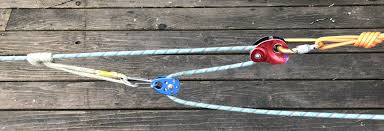
MECHANICAL ADVANTAGE - Mechanical advantage (MA) is the factor by which a machine multiplies the force put into it. Consider lifting a weight with rope and pulleys. A rope looped through a pulley attached to a fixed spot and attached to the weight is called a single fixed pulley. It has a MA = 1, meaning no mechanical advantage (or disadvantage) however advantageous the change in direction may be. A single moveable pulley has a Mechanical Advantage = 2. Consider a pulley attached to a weight being lifted. A rope passes around it, with one end attached to a fixed point above, e.g. a barn roof rafter, and a pulling force is applied upward to the other end with the two lengths parallel. In this situation the distance the lifter must pull the rope becomes twice the distance the weight travels, allowing the force applied to be halved. If an additional pulley is used to change the direction of the rope, e.g. the person doing the work wants to stand on the ground instead of on a rafter, the mechanical advantage is not increased. By looping more ropes around more pulleys, we can continue to increase the mechanical advantage. If we have two pulleys attached to the rafter, two pulleys attached to the weight, one end attached to the rafter, and someone standing on the rafter pulling the rope, we have a mechanical advantage of four. If we add another pulley so that someone may stand on the ground and pull down, we still have a mechanical advantage of four.

Mechanical Advantage — Alpine Savvy
............................................................................................................................................
Mechanical Advantage | CK-12 Foundation
Mechanical Advantage

What is Mechanical Advantage
EDinformatics.com


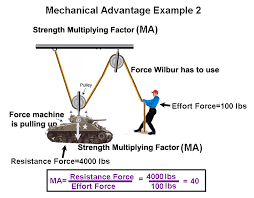
In physics and engineering, mechanical advantage (MA) is the factor by which a machine multiplies the force put into it.
The mechanical advantage can be calculated for the following simple machines by using the following formulas:
·      Lever: MA = length of effort arm ÷ length of resistance arm. 
·      Wheel and axle: A wheel is essentially a lever with one arm the distance between the axle and the outer point of the wheel, and the other the radius of the axle.
Typically, this is a fairly large difference, leading to a proportionately large mechanical advantage.
This allows even simple wheels with wooden axles running in wooden blocks to still turn freely, because their friction is overwhelmed by the rotational force of the wheel multiplied by the mechanical advantage. 
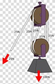
Mechanical Advantage transparent background PNG cliparts free ...·      Pulley: Pulleys change the direction of a tension force on a flexible material, e.g. a rope or cable.
In addition, pulleys can be "added together" to create mechanical advantage, by having the flexible material looped over several pulleys in turn.
More loops and pulleys increase the mechanical advantage. 
Mechanical advantage
Consider lifting a weight with rope and pulleys.
A rope looped through a pulley attached to a fixed spot, e.g. a barn roof rafter, and attached to the weight is called a single fixed pulley.
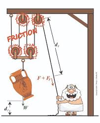
Actual Mechanical Advantage | Engineering Expert Witness BlogIt has a MA = 1, meaning no mechanical advantage (or disadvantage) however advantageous the change in direction may be.
single moveable pulley has a Mechanical Advantage = 2. Consider a pulley attached to a weight being lifted.
A rope passes around it, with one end attached to a fixed point above, e.g. a barn roof rafter, and a pulling force is applied upward to the other end with the two lengths parallel.
In this situation the distance the lifter must pull the rope becomes twice the distance the weight travels, allowing the force applied to be halved.
Note: if an additional pulley is used to change the direction of the rope, e.g. the person doing the work wants to stand on the ground instead of on a rafter, the mechanical advantage is not increased.
By looping more ropes around more pulleys, we can continue to increase the mechanical advantage.
For example, if we have two pulleys attached to the rafter, two pulleys attached to the weight, one end attached to the rafter, and someone standing on the rafter pulling the rope, we have a mechanical advantage of four.
Again note: if we add another pulley so that someone may stand on the ground and pull down, we still have a mechanical advantage of four.
What is Mechanical Advantage? flashcards on TinycardsHere are examples where the fixed point is not obvious:
A man sits on seat that hangs from a rope that is looped through a pulley attached to a roof rafter above. The man pulls down on the rope to lift himself and the seat.
The pulley is considered a movable pulley and the man and the seat are considered as fixed points; MA = 2.
A velcro strap on a shoe passes through a slot and folds over on itself. The slot is a movable pulley and the Mechanical Advantage =2.
Two ropes laid down a ramp attached to a raised platform. A barrel is rolled onto the ropes and the ropes are passed over the barrel and handed to two workers at the top of the ramp.
The workers pull the ropes together to get the barrel to the top. The barrel is a movable pulley and the MA = 2.
If the there is enough friction where the rope is pinched between the barrel and the ramp, the pinch point becomes the attachment point.
This is considered a fixed attachment point because the rope above the barrel does not move relative to the ramp.
Alternatively, the ends of the rope can be attached to the platform.
·      Inclined plane: MA = length of slope ÷ height of slope 
Generally, the mechanical advantage is calculated thus:
·      MA = (the distance over which force is applied) ÷ (the distance over which the load is moved) 
also, the Force exerted IN to the machine × the distance moved IN will always be equal to the force exerted OUT of the machine × the distance moved OUT.
For example; using a block and tackle with 6 ropes, and a 600-pound load, the operator would be required to pull the rope 6 feet, and exert 100 pounds of force to lift the load 1 foot, therefore:
·      (force IN 100 × distance IN 6) = (force OUT 600 × distance OUT 1
·      or, WORKin = WORKout
This requires an ideal simple machine, meaning that there are no losses due to friction or elasticity. If friction or elasticity exist in the system efficiency will be lower; Work in will be greater than Workout
Mechanical advantage also applies to torque. A simple gearset is able to multiply torque.
Type of mechanical advantage
There are two types of mechanical advantage:
1.Ideal mechanical advantage (IMA) 
2.Actual mechanical advantage (AMA) 
Ideal mechanical advantage
The ideal mechanical advantage is the mechanical advantage of an ideal machine.
It is usually calculated using physics principles because we have no ideal machine. It is 'theoretical'.
The IMA of a machine can be found with the following formula:
IMA = DE / DR
where DE equals the effort distance and DR equals the resistance distance.
Actual mechanical advantage
The actual mechanical advantage is the mechanical advantage of a real machine.
Actual mechanical advantage takes into consideration real world factors such as energy lost in friction. In this way, it differs from the ideal mechanical advantage, which, is a sort of 'theoretical limit' to the efficiency.
The AMA of a machine is calculated with the following formula:
AMA = R / Eactual
where
R is the resistance force, 
Eactual is the actual effort force.

EDUCATION FOR THE INFORMATION AGE
Lever Mechanical Advantage Force Tongs Tweezers, PNG, 1714x771px ...