
........................................................................................................................................................
Engineering Beam Theory
 What
is engineering beam theory?
What
is engineering beam theory?
Definition
of a beam
A structural element or
member subjected to forces and couples along the members longitudinal axis.
The member typically
spans between one or more supports and its design is generally governed by
bending moments.
Euler-Bernoulli Beam Theory
The Euler-Bernoulli equation describes the relationship between
the applied load and the resulting deflection of the beam and is shown
mathematically as:
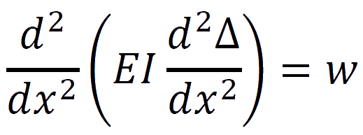
Where w is the
distributed loading or force per unit length acting in the same direction as y
and the deflection of the beam Δ(x) at some position x.
E is the modulus of
elasticity of the material under consideration and I is the second moment of
area calculated with respect to the axis which passes through the centroid of
the cross-section and is perpendicular to the applied load.
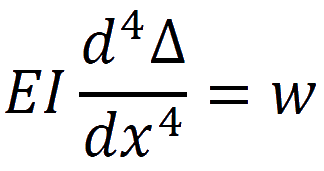
If EI or the flexural
rigidity does not vary along the beam then the equation simplifies to:
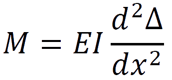
Once the deflection due
to a given load has been determined the stresses in the beam can be calculated
using the following expressions:
The bending moment in the beam:
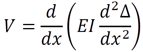
The shear force in the
beam:
Support connections and
reactions
There are four different types of connection that are commonly
encountered when dealing with beams and each one determines the type of load
that the support can resist as well as the overall load bearing capacity of not
only the member under consideration but also the system in which the member is
a part of.
Roller supports: are free to rotate and
translate along the surface upon which the roller rests and as a result are
unable to resist lateral forces. Such supports are subjected to a singular
reaction force acting perpendicular to and away from the surface.
Pinned Supports: allow the member or beam
to rotate (sometimes in only one direction), but not to translate in any
direction, that is, they can resist both vertical and horizontal forces but not
bending moments.
Fixed Supports: restrain against both
rotation and translation and resist both vertical and horizontal forces as well
as bending moments.
Simple Supports: are free to rotate and
translate along the surface which they rest in all directions but perpendicular
to and away from the surface. Simple supports are dissimilar to roller supports
in that they cannot resist lateral loads of any magnitude.
Types of Beams
Simply support beam: freely supported at each
end the member is free to rotate at the end bearing points and has no
resistance to bending moments. The end supports of the beam are capable of
exerting forces on the beam but will rotate as the member deflects under any
loads.
Fixed beam: restrained at each end of the member
the end points are restricted from rotation and movement in both the vertical
and horizontal directions.
Cantilever beam: a member fixed at one end
only with the other end free to rotate and move freely in both vertical and
horizontal directions.
Overhanging: a simple beam that extends beyond its
supports at one or both ends.
Continuous: a beam extending over more than two
supports.
Accuracy of engineer's beam
theory
Because of the assumptions, a general rule of thumb is that for
most configurations, the equations for flexural stress and transverse shear
stress are accurate to within about 3% for beams with a length-to-height ratio
greater than 4.
The conservative nature
of structural design (load factors) in most instances compensate for these
inaccuracies.
It is also important to
understand and to give consideration to the type of material/s which makes up
the beam, the way the beam deforms, the geometry of the beam including the
cross-sectional area and the internal equilibrium present.
Assumptions and limitations
· The
cross-section of the beam is considered small compared to its length meaning that
the beam is long and thin.
· Loads
act transverse to the longitudinal axis and pass through the shear centre
eliminating any torsion or twist.
· Self-weight
of the beam has been ignored and should be taken into account in practice.
· The
material of the beam is homogenous and isotropic and has a constant Young's
modulus in all directions in both compression and tension.
· The
centroidal plane or neutral surface is subjected to zero axial stress and does
not undergo any change in length.
· The
response to strain is one dimensional stress in the direction of bending.
· Deflections
are assumed to be very small compared to the overall length of the beam.
· The
cross-section remains planar and perpendicular to the longitudinal axis during
bending.
· The
beam is initially straight and any deflection of the beam follows a circular
arc with the radius of curvature considered to remain large compared to the
dimension of the cross section.
Curved Beams and Arches
Whilst the design of curved beams is identical to that of straight
beams when the dimensions of the cross-section are small compared to the radius
of curvature the primary difference between curved beams and arches is that the
curvature has been increased to a point where axial forces become significant
in arches.
A note about bending moments
In structural engineering the positive moment is drawn on the
tension side of the member allowing beams and frames to be dealt with more
easily.
Because moments are
drawn in the same direction as the member would theoretically bend when loaded
it is easier to visualise what is happening. StructX has adopted this way of
drawing bending moments throughout.
A selection of beam equations along with relevant engineering
calculators can be found Here.
"Good
engineers don't need to remember every formula; they just need to know where
they can find them."
StructX was
created in an effort to provide a comprehensive and freely accessible resource
for the structural engineering community - "Good engineers don't need to
remember every formula; they just need to know where they can find them".
Fundamentally, StructX is an ever adapting source of formulas, data, properties
and techniques commonly adopted by structural engineers worldwide.
The
information provided throughout this website has been created based on existing
theories or adapted from well-established resources both online and offline.
Most of the information provided by StructX is already available on the web
free of charge with the only difference being that StructX brings all this
information together into one handy resource. References have been provided
wherever possible to allow the user to attain additional information or to
confirm authenticity, originality and/or accuracy of the material provided.
No comments:
Post a Comment